English
 عربى
 中文简体



A 45-metre coaster easing into a lock at three knots is the clearest test of a stern rudder. At that speed the hull alone pushes far too little water past the blade to steer, and the vessel only answers the wheel because the propeller is driving a fast, swirling column of water straight over the foil.
That single fact explains both the design logic and the buying decision. A stern rudder is the profiled blade hung on the vessel's centreline aft of the propeller, and it turns the hull by generating sideways lift rather than by "blocking" water. The short answer for anyone specifying one: use a balanced or semi-balanced blade with roughly 20 to 28 percent of its lateral area forward of the stock axis, limit travel to 35 degrees each side, and size the steering gear from the rudder torque curve at maximum helm, in reverse as well as ahead, instead of from hull length. The sections below explain why those numbers matter and where they can safely be adjusted.
Content
- Why the stern position beats a side-mounted oar
- How the blade actually turns the hull
- Stern rudder types and where each one fits
- Matching rudder torque to the steering gear
- Eight numbers to pin down before ordering
- Installation, tolerances and the wear points that matter
- Procurement risks worth pricing in
- Frequently asked questions
Why the stern position beats a side-mounted oar
A stern rudder outperforms a side steering oar mainly because it works inside the propeller race, where water velocity over the foil is highest.
Lift rises with the square of flow velocity. When a propeller accelerates the water past the blade, local speed through the rudder aperture can roughly double, and the side force at the same rudder angle can rise several-fold. That is the physical reason the centreline stern rudder displaced the side oar across Northern Europe between roughly 1200 and 1500, well after Chinese shipyards had already adopted it. The second reason is symmetry: a blade on the centreline produces the same force port and starboard, while a side oar behaves differently as the hull heels.
| Aspect | Stern rudder | Side oar |
|---|---|---|
| Position | Centreline, directly aft of the propeller | One quarter, offset from the shaft line |
| Main force source | Hydrodynamic lift plus propeller race | Hull flow and oar sweep angle |
| Authority at low speed | High, even at zero boat speed with the engine turning | Poor unless the oar is physically swept |
| Behaviour when heeled | Predictable, force stays symmetric | Asymmetric, harder to correct |
| Structural demand | Rudder stock, neck bearing, pintle or internal bearings | Oar blade, fulcrum and hull-side reinforcement |
How the blade actually turns the hull
A stern rudder steers by generating lift, and lift depends far more on angle of attack than on blade area alone.
Angle of attack and stall
Up to roughly 30 to 35 degrees, side force rises almost linearly with rudder angle. Beyond that point the flow separates from the low-pressure side, lift falls away, drag climbs and the blade starts to vibrate. This is why nearly every commercial steering system stops at 35 degrees each side, and why classification rules require the gear to swing the rudder from 35 degrees on one side to 30 degrees on the other in not more than 28 seconds at rated conditions.
The propeller race and stopped-speed steering
A rudder directly behind the propeller keeps producing force with the engine turning even when the hull is stationary. Berthing and tug work rely on this: the blade is not steering the ship, it is steering the wash. Blade position relative to the propeller aperture therefore matters as much as blade shape. Too large a gap and the race spills around the blade edges; too small a gap and tip erosion accelerates.
Balance ratio and stock position
Balance ratio is the share of lateral area placed forward of the stock axis, and it is the single most effective way to reduce steering torque. Moving the centre of pressure closer to the axis cuts the lever arm, so a well-balanced blade may need only a fraction of the torque of an unbalanced one of identical area. Typical commercial blades balance 20 to 28 percent of area ahead of the stock; skeg-supported semi-balanced blades use a similar figure while the skeg carries bearing loads that would otherwise load the stock.
Stern rudder types and where each one fits
Four families cover nearly all commercial work, and the decisive difference is how the blade is supported, not the outline of the foil.
| Type | Support and pivot | Typical vessels | Main trade-off |
|---|---|---|---|
| Unbalanced, skeg-hung | Stock at the leading edge, whole area aft | Small craft, slow workboats, barges | Simple and robust, but the highest steering torque for its area |
| Semi-balanced | Part of the area ahead of the stock, supported by a skeg, horn or internal bearings | Coasters, fishing vessels, tugs, offshore support | Moderate torque with useful protection of the propeller |
| Fully balanced spade | Stock is the only support, 20 to 30 percent of area ahead | Fast ferries, yachts, patrol and naval craft | Lowest torque and cleanest flow, but no protection if the blade strikes ground or debris |
| Flap or hinged trailing edge | Main blade plus a hinged flap on the trailing edge | Ferries and vessels needing high lift at moderate helm | More lift per degree of helm, but extra linkages and bearings to maintain |
Matching rudder torque to the steering gear
The steering gear should be sized from the rudder's peak torque, and for a balanced blade that peak usually appears somewhere between 25 and 35 degrees of helm, ahead and again astern, not at midships.
Rudder torque is the normal force on the blade multiplied by the distance from its centre of pressure to the stock axis. That lever arm changes with angle, so the torque curve rises, flattens and can fall again before maximum helm is reached. Two figures belong in every enquiry: the torque at 35 degrees with the ship at full speed ahead, and the torque in reverse, which is frequently overlooked and is often the case that overloads the actuator. Most builders apply a design margin of about 1.5 times the calculated ahead torque to cover fouling, weather helm and transient impact loads, and the gear itself must be certified by the vessel's classification society.
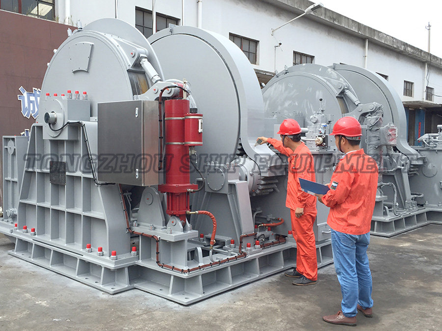
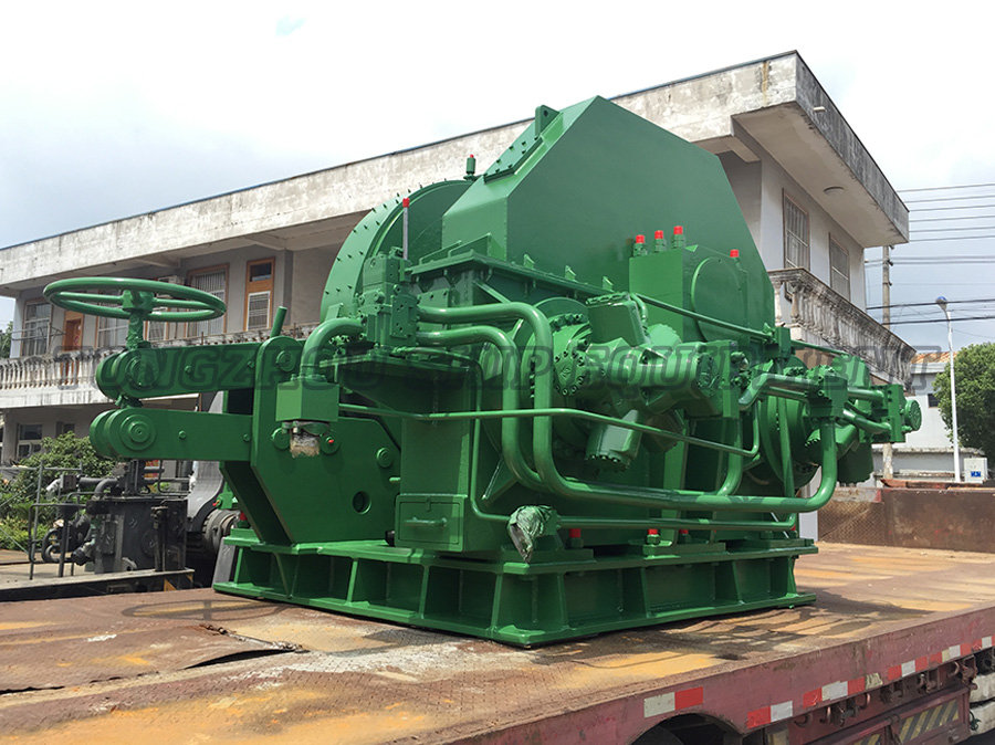
For larger rudder torque, the conventional solution is a tiller arm driven by two opposed rams, an arrangement covered in the fork-type actuation devices range and widely used on cargo vessels and tugs. Smaller blades, or installations where space around the stock is tight, are usually better served by a rotary actuator.
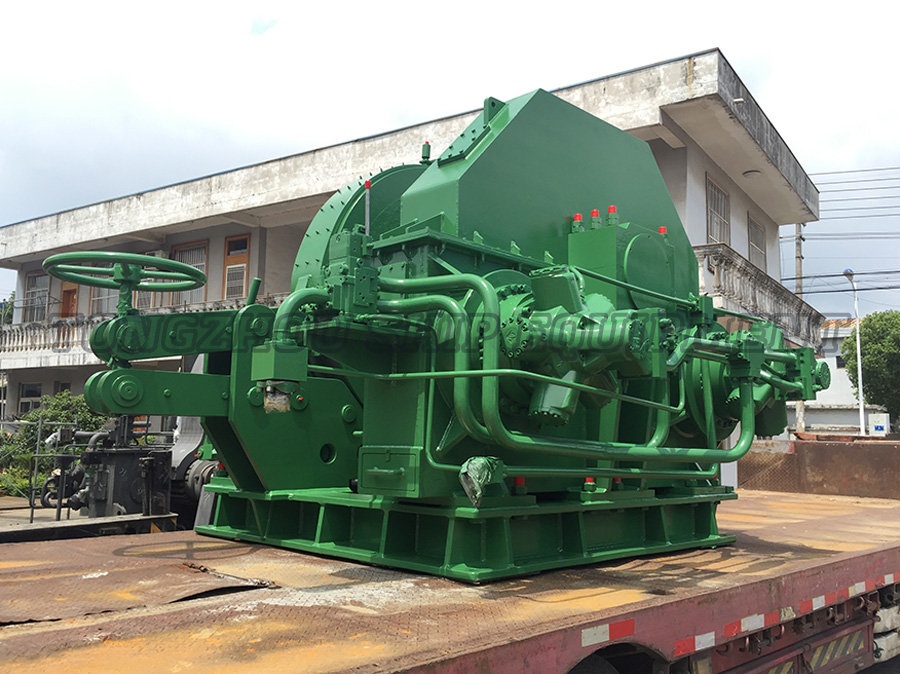
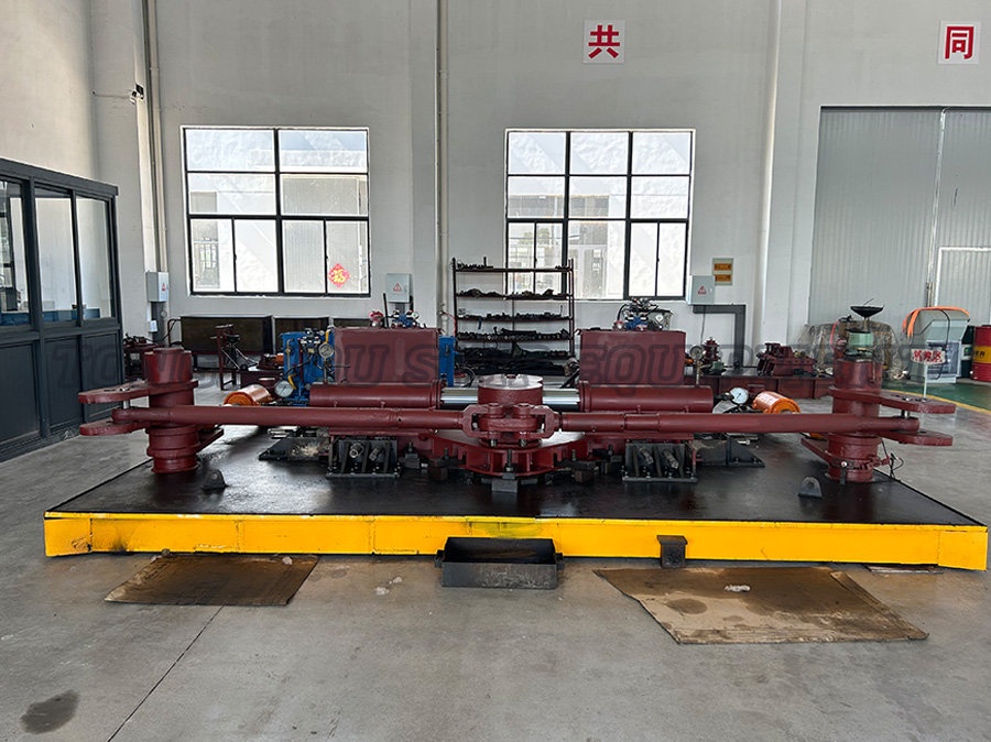 Fork type hydraulic steering gear SuppliersTongzhou products have successively obtained recognition from major ship inspections such as ZC, CCS, ZY, BV, ABS, LR, DNV, NK, KR, BKI, etc. The products are exported...View Product →
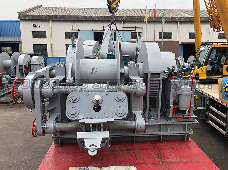
Torque capacity is the first filter, but not the only one. Stroke, mounting footprint and the position of the rudder trunk decide whether a tiller-driven or a rotary unit can physically be installed. Published ranges from one deck machinery maker run from 25 kN·m to 1350 kN·m for fork-type hydraulic steering gear and from 8 kN·m to 600 kN·m for swing-cylinder units, which shows how sharply the two families divide by vessel size.
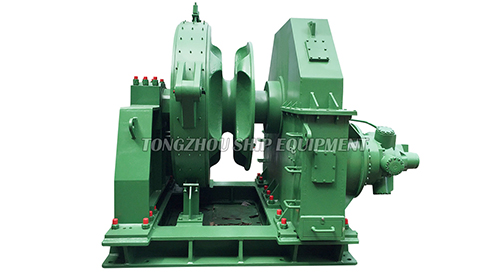
 Swing Cylinder Hydraulic Steering Gear SuppliersTongzhou products have successively obtained recognition from major ship inspections such as ZC, CCS, ZY, BV, ABS, LR, DNV, NK, KR, BKI, etc. The products are exported...View Product →
Whatever the actuator, the torque it can deliver has to be checked against the high-torque actuation units specification at the rated system pressure, not at the relief valve setting, and the pump set has to hold that pressure continuously during a long turn in a seaway.
Eight numbers to pin down before ordering
A stern rudder order goes wrong when the specification leaves a number open, and eight of them account for most disputes.
- Rule length, class notation and the society that will witness the test, since the steering gear needs its own certificate.
- Rudder area ratio, typically between about 1/50 and 1/70 of the submerged lateral area (length times draught) for a single-screw cargo vessel, rising to 1/40 or more for tugs and vessels needing tight manoeuvring.
- Maximum rudder angle and angular rate, usually 35 degrees each side with a swing time measured against the rule requirement.
- Stock diameter, material grade and the coupling detail, whether keyed taper, keyless friction or flange.
- Torque at each specified angle, ahead and astern, with the design margin stated explicitly.
- Bearing type and lubrication, self-lubricating bush or grease nipple, plus the replacement interval.
- Coating system and anode allowance for the wetted blade and the aperture area.
- Documentation set: material certificates, non-destructive testing reports, factory acceptance test record and spare seal kit.
Installation, tolerances and the wear points that matter
Most stern rudder complaints in service trace back to alignment and bearing clearance at installation rather than to the foil itself.
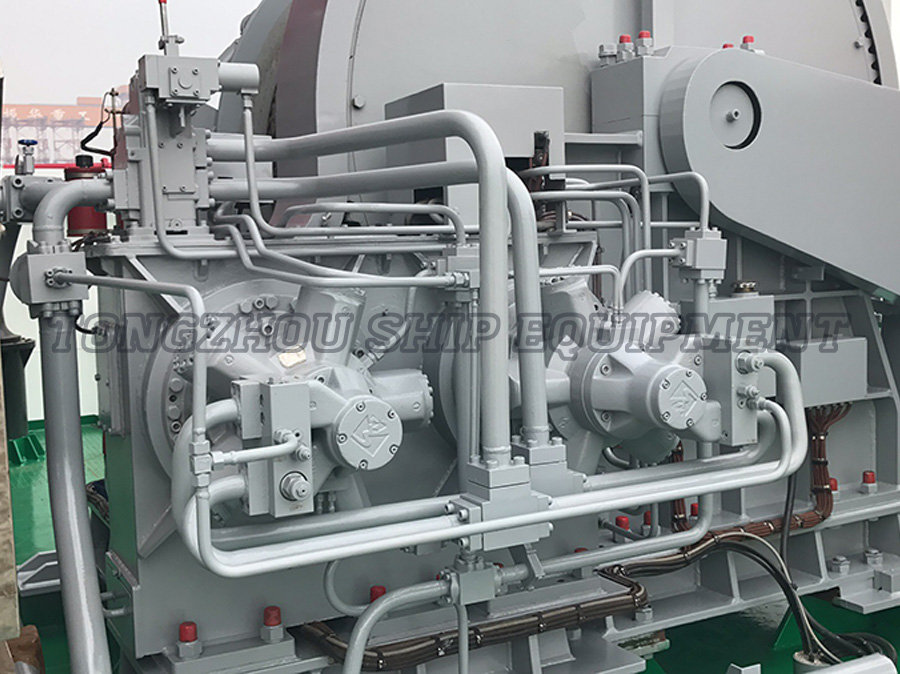
The stock must sit vertically within the maker's tolerance before the actuator is coupled, and the tiller or rotary hub should be fitted after the hull welds are complete, because welding distortion moves the deck ring and preloads the neck bearing. Once the hydraulic circuit is closed, commissioning pressure, filtration and air removal decide whether the gear runs quietly for years or chatters from the first voyage.
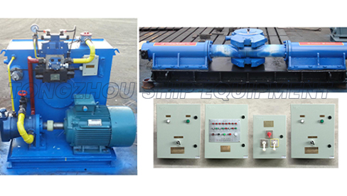
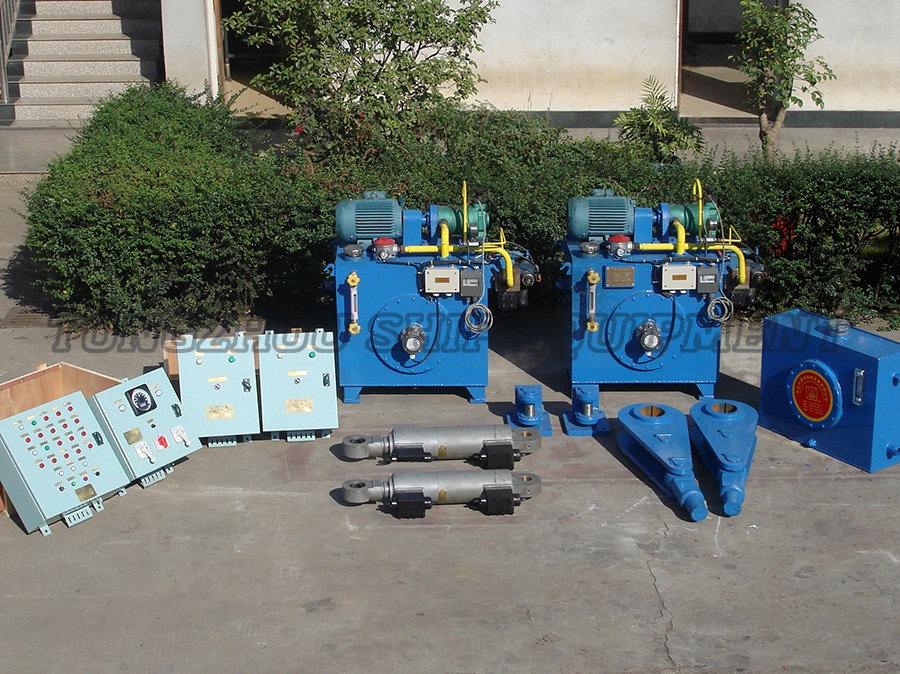
 Hydraulic Power Unit ManufacturersTongzhou products have successively obtained recognition from major ship inspections such as ZC, CCS, ZY, BV, ABS, LR, DNV, NK, KR, BKI, etc. The products are exported...View Product →
| Check point | Why it matters | Typical action |
|---|---|---|
| Stock verticality and neck bearing alignment | Misalignment loads the bearing and the actuator seal | Verify before coupling, ream or shim after welding |
| Pintle and gudgeon clearance | Slack shows up as a dead band at the wheel and as knocking | Renew the bush when play exceeds the maker's limit; a class survey item |
| Blade-to-aperture gap | Too small a gap accelerates cavitation erosion on the blade edge | Keep the drawing clearance and inspect edges at each docking |
| Coating and anodes | Pitting on the leading edge grows into cracking | Touch up at every dry docking, replace anodes on schedule |
| Hydraulic oil condition | Water ingress or particle load wears pumps and valves | Sample at fixed intervals, change filters on evidence, not on habit |
Procurement risks worth pricing in
The expensive mistakes in stern rudder procurement are specification gaps, not price differences between suppliers.
- Quoting torque at 35 degrees only, and then discovering that the reverse torque exceeds the actuator rating during harbour manoeuvring.
- Ordering the steering gear and the rudder from different suppliers without a shared interface drawing for stock diameter, keyway and tiller bore.
- Accepting a factory test at reduced pressure, which hides a pump set that cannot hold rated torque through a sustained turn.
- Leaving classification society witnessing out of the purchase order, so the certificate arrives after the vessel's survey window.
- Forgetting the wearing parts list, which turns a routine seal replacement into a weeks-long procurement exercise.
Frequently asked questions
Is a stern rudder the same thing as a balanced rudder?
No. Stern describes where the blade is mounted; balanced describes how much of its area sits ahead of the stock axis. A stern rudder can be unbalanced, semi-balanced or fully balanced, and the balance decision is what sets the steering gear size.
Can a stern rudder steer a ship that is not moving?
Yes, as long as the propeller is turning and the blade sits in the race. The force then comes from the accelerated wash rather than from hull speed, which is why berthing procedures rely on short engine bursts rather than on helm alone.
Why does the wheel feel slack around midships?
Lost motion near the neutral position usually points to wear in the pintle bush, the neck bearing or the tiller connection, or to air in the hydraulic circuit. It is a mechanical clearance symptom and rarely a foil problem.
Does rudder profile matter more than rudder area?
Area sets the ceiling on available force, while profile decides how much of that ceiling can be reached before the flow stalls. A well-profiled blade at 35 degrees will usually outperform a larger flat plate pushed to the same angle.
How often should the steering gear be serviced?
Follow the maker's manual and the class survey cycle: oil analysis at fixed intervals, filters on evidence, and a full inspection of bearings, seals and linkages at every dry docking.
Get the balance ratio, the torque curve and the actuator interface right at the enquiry stage, and a stern rudder becomes one of the least troublesome items on the vessel. Leave any one of them open, and the wheelhouse will feel it on the first windy berthing.